Snyper Survey Terminology
The information obtained from the SNYPER about the cellular environment is both comprehensive but also probably very daunting for many users. Different users will want to use different depths of the information provided. Whether viewed only on the SNYPER itself or on the files produced by the SNYPER, the information presented is consistent.
The information obtained from the SNYPER about the cellular environment is both comprehensive but also probably very daunting for many users. Different users will want to use different depths of the information provided. Whether viewed only on the SNYPER itself or on the files produced by the SNYPER, the information presented is consistent.
While many of the terms used are common to 2G, 3G and 4G networks, in many cases the range of values returned for any parameter can be different dependent on the generator of technology surveyed.
4G Survey Terms
Cellular Network
The mobile phone network which carries not only voice but also data. Often referred to as the GSM network, GSM being the first digital mobile telephony network.
LTE
Long Term Evolution, the 4G cellular network.
MIMO
Multiple In Multiple Out. A method of increasing the capacity of a radio network by using multiple transmit and receive antennas.
E-UTRA
Evolved UMTS Terrestrial Radio Access. The radio air interface of the 4G LTE network.
IMEI
International Mobile Equipment Identity. A 15 decimal digit number unique to the cellular device.
ITU
International Telecommunication Union. A United Nations agency responsible for standardizing telecommunications.
VoLTE
Voice over LTE. The mechanism by which packetized voice traffic is carried over the LTE network.
Cell
All cells discovered in the survey are ranked by signal strength, where cell number 1 is the cell with the strongest signal, 2 is the next strongest, and so on.
Index
This is a unique index number used by the SNYPER to identify a cell. Where the survey is a single survey, the cell number and index number are the same. With multiple surveys that the Index and the Cell numbers can be different as the order of strength of the cells can differ between surveys.
Seen (Graphyte ONLY)
Applicable to all surveys where logging has been used. It is the count of how many times that the cell was seen, and (in brackets) what percentage of the surveys made that represents. There is usually (but not always) a good correlation between received signal strength and how many times that a cell is seen.
EARFCN
This number defines the exact uplink and downlink frequencies used by the cell. The standard allows for any number between 0 and 262143, although in practice on the SNYPER the user will only see numbers in the range 0 to 27659. This number may be looked up in the LTE standard to determine the exact radio frequencies used.
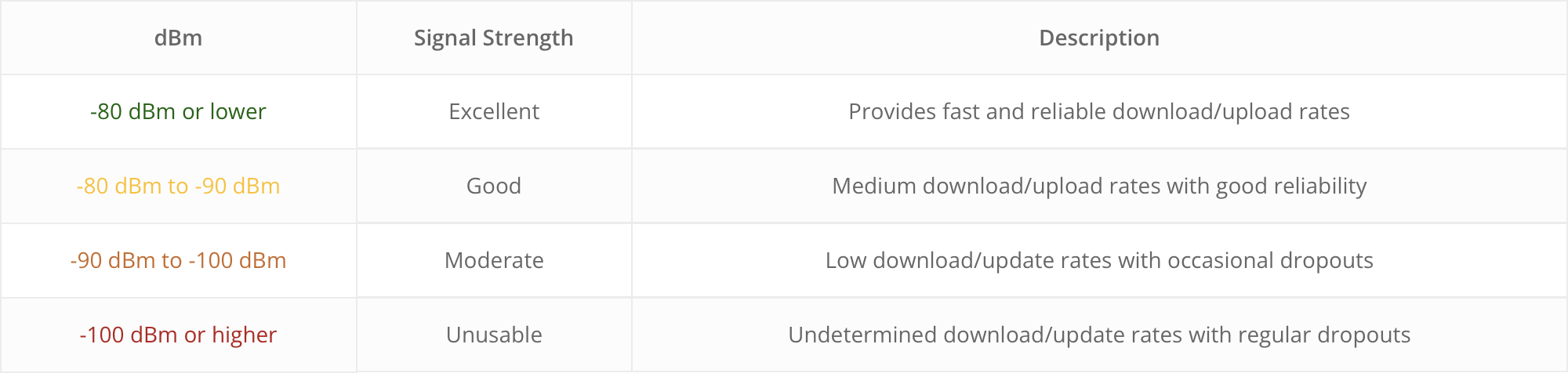
dBm or AV dBm
The measured signal strength of the network in dBm. AV dBm is the average of dBm of a multi-cycle survey.
RSSI or AV RSSI
This measurement is derived from the dBm measurement. It is the Received Signal Strength Indication which is obtained by looking up the dBm measurement in a table in the GSM standard. AV RSSI is the average RSSI of a multi-cycle survey.
MCC
Mobile Country Code. It identifies the country from which the network is originating. This should mean the country in which the base station is located. Unfortunately, there are some exceptions to this so it cannot always be used as a positive country indication. Typically used with the MNC to uniquely identify the network discovered.
MNC
Mobile Network Code. This identifies the network operator in conjunction with the MCC. Some network operators such as Vodafone operate in many countries. It cannot be assumed that such network operators will have the same MNC in all countries in which they operate.
% or AV %
This measurement is derived from the dBm measurement. It is the measured signal strength expressed as a percentage of the maximum possible signal strength which could be obtained. AV % is the average percentage of a multi-cycle survey.
LAI
Location Area Identification. Comprises the MCC, MNC and the LAC to uniquely define a geographical location.
CellID
This is the Cell Identifier number assigned to a cell by its operator. It may be any number between 0 and 268435455. For a 4G network, this field is really called the LCID (Long Cell ID) and comprises the 12-bit RNC-ID concatenated with the 16-bit Cell ID. When combined with the TAC a base station may be uniquely identified.
TAC
Tracking Area Code. It may be any number between 1 and 65535, excluding 65534. It is assigned by the network operator and may be changed periodically for performance reasons (so beware if using it in a database). The TAC is assigned to a specific geographical area and will be assigned to all base stations in the defined area.
Band
Channel number and designation of the surveyed channel. Derived from the received EARFCN.
PCI
Physical CellID. Visible when using Advanced mode and Engineer mode. This is the Physical layer Cell Identity (PCI). It may be any number between 0 and 503. The PCI determines how the signalling works on the radio interface and has some similarity to the way that scrambling codes are used on UMTS networks. It is not used as an identity within the network.
RSRP
Reference Signal Received Power. This is like an RSSI measurement, and like RSSI is measured in dBm. RSSI indicates the total power in the channel passband which includes noise signals and other interference. The less negative, the stronger the signal. RSRP differs in that it measures only the power of the LTE reference signals and is therefore a better indication of the signal strength of an active connection. RSRP and/or RSRQ are used by the network to determine cell selection.
RSRQ
Reference Signal Received Quality. This is the ratio of the RSRP measurement to the RSSI measurement measured in dB. The less negative, the better the quality of the signal. RSRP and/or RSRQ are used by the network to determine cell selection, although RSRP is usually chosen as the primary selection method.
BW
Visible when using Advanced mode and Engineer mode. This is the downlink bandwidth in MHz.
DL (MHz)
Visible when using Engineer mode. This is the downlink frequency in MHz of the channel. This is derived from the received EARFCN.
UL (MHz)
Visible when using Engineer mode. This is the uplink frequency in MHz of the channel. This is derived from the received EARFCN.
Network Signal
This bar graph shows the relative strengths of the networks. The bars show percentage strength measurement. They are colour coded:
55 – 100 = green
25 – 54 = amber
0-24 = red
The thresholds for the colours are arbitrary and assigned by Siretta as a quick visual que to network quality. The network operator listed is a look-up of the MCC and MNC codes. If a network operator is new or changes their name it is possible that this lookup could be incorrect. Due to it being impossible for Siretta to monitor every network in every country continuously, please report any inaccuracies so that they can be corrected in a firmware update.